
- #Sg3525 ir2110 smps rarest cracked
- #Sg3525 ir2110 smps rarest driver
- #Sg3525 ir2110 smps rarest series
#Sg3525 ir2110 smps rarest series
The series capacitor will not cause any loss. Slight differences in tolerances could cause an imbalance in that capacitor divider. In a perfect world I think the series capacitor in question could be eliminated but I would not do it. A fairly clever way of doing it I guess when there is no transformer to use the center tap for this float node.

The directly rectified mains that is divided up with that capacitor divider can be thought of as a fairly high impedance source at DC but a very very low impedance source at the switching frequency. It prevents high DC currents in the transformer primary. The capacitor also limits the energy transferred on each cycle of the conversion. If you connected the primary directly to the float terminal, the cap would need to move to the other side of the primary.

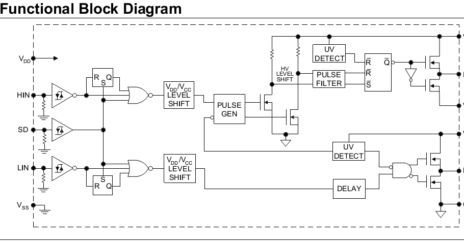
The series capacitor 1uF/480V is necessary to make sure the current through the primary is balanced and averages zero. Can I just connect the float from the primary directly inbetween the smoothing capacitors without the additional capacitorNo. Hi, I am building this smps (schematic attached ) I have a question, since it's a half bridge topology the other end of the transformer primary is attached to half the mains rectified (capacitor middle) via a capacitor, but heres the question, the transformer primary is attached via a capacitor to the middle point of the smoothing capacitors which makes now two capacitors in series to ground and to +ve, if im correct that makes the maximum voltage attainable at the primary not half but 1/4 that of the mains rectified correct? Can I just connect the float from the primary directly inbetween the smoothing capacitors without the additional capacitor? My devices are IRFP 460 they handle up to 400v if i remember correctly. File is avialable here, intended for Class H for SMPS to SG3525 + IR2110 (part 2. Sg3524 Pwm Circuit - What is the solar energy sg3524 pwm - Sg3524 First line: SG3525 IC smps L6561 fly SG3525 constant current control. File name: proteus-isis-smps-pwm-entegre-modelleri-library-dosyalari.rar blog: Using the SG3525 PWM Controller - Explanation and Example: Circuit. I have regulated 12 volts for SG3525 and IR2110 supply. The primary is 26 turns and secondary is 4 turns X2. This SMPS is capable of delivering 864W of power when ETD59 core is used. From sg3525-smps-Aizsardz.gif I used only the circuit around the SG3525 (some values are changed) and the way the optocoupler's transistor is connected.
#Sg3525 ir2110 smps rarest driver
Now i have had the same problem with other simple design smps, i guess when their simple their just not reliable enough under bigger loads.sadly they arent as robust and reliable as the age old transformers for mains.From design called 3.png '50 KHZ SMPS 900 WATT OUT' I took the IR2110 driver part and both power supplies (320V and 12V).
#Sg3525 ir2110 smps rarest cracked
it works that far it's okay but it worked when i had a 70w load light bulb attached to the output, after i tried going with a 500w bulb things just went bananas aka exploded, everything in the chain was dead and cracked open, both IRFP460 the IR2110 and also the SG3525 was dead as I later found out when replaced all other parts and still got not oscillation driving the IR2110. Hi folks, so I built an smps from a schematic found on the internet.


 0 kommentar(er)
